Best Of The Best Tips About How To Draw Gear Teeth

#engineering #tutorials the involute gear profile is the most commonly used system for gearing today, with cycloid gearing still used for some specialties su.
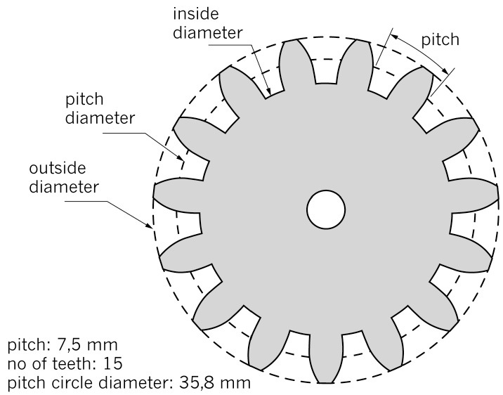
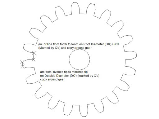
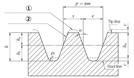
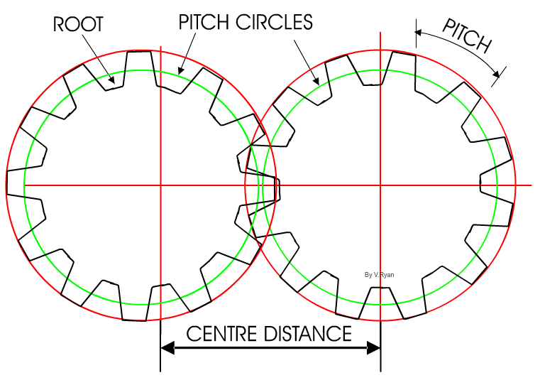
How to draw gear teeth. Now extrude the tooth polyline by 25mm. Array>>polar array>> and select the tooth profile extruded to array and the center point be. Begin by laying out the pitch, root.
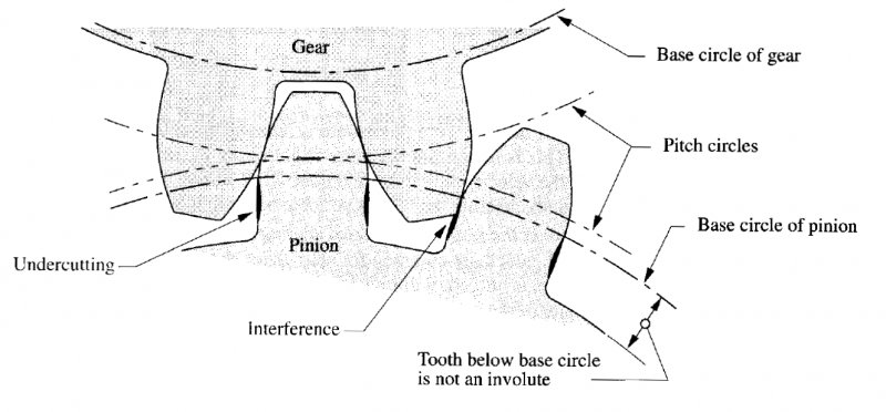
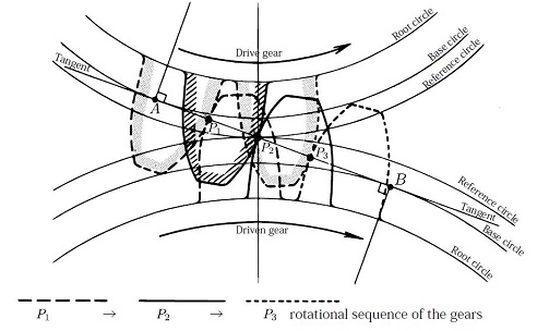
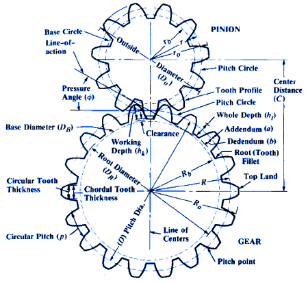
In designing gear teeth a primary consideration is to select that portion of the involute for the teeth which will best meet requirements. These gear teeth will not have an involute, but will have straight angled teeth according to the pres. Diagrams are sized at 1/3 dp or three times the size of a 1 dp tooth, equivalent to 76.2 module.
Divide the scaled dimensions by the three times the diametral pitch of the tooth size. Input the following parameters in our free gear dxf generator: This video tutorial will be very helpful to our engineerin.
Using this example you will be able to draw a spur gear having any number of teeth and pitch. Make a circle of 50mm radius. Therefore, for a known imld to be transmitted, the pitch is chosen which in turn determines 'the.
Mainly this channel for engineering students, such as btech/be, diploma engineering (polytechnic). This video will show you how to draw teeth in autocad. This video details the process of drawing an involute spur gear by hand in solidworks.
3 a series of parallel involutes, a,b,ca.nd. The number of gear teeth and the diametral pitch regulate the size of the gear.


